


Russian Federation
The article discusses the methodology for calculating corrugated metal structures used as culverts based on the semi-analytical finite element method. The calculation is carried out according to a non-deformable scheme using the load dependences obtained on the basis of the structural mechanics of bulk solids. Significant differences in the nature of the stress-strain state of corrugated structures in comparison with smooth shells is revealed.
corrugated metal shells, semi-analytical finite element method, stress-strain state, series
Introduction. The peculiarity of calculating culverts under road embankments is that they work in conjunction with the surrounding soil. The soil acts as the base of the pipe, as well as the medium that transmits above-ground loads. In addition, the dead weight of the soil also creates a load on the pipe.
Culverts are usually taken rigid and they are calculated according to an undeformed scheme, not taking into account the lateral rebound of the soil. In [1,2], the following expressions are given for the normal and tangential components of the load on a cylindrical shell (Fig. 1), obtained on the assumption that the culvert does not affect the limiting stress state of the surrounding soil, and the soil is a loose body:
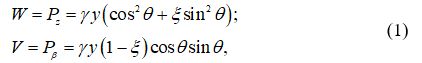
where ![]() – the distance from the point under consideration to a surface mound; R – shell radius;
– the distance from the point under consideration to a surface mound; R – shell radius; ![]() – lateral pressure coefficient, φ – angle of internal friction, γ – specific gravity of the soil.
– lateral pressure coefficient, φ – angle of internal friction, γ – specific gravity of the soil.
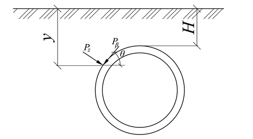
Figure 1. Components of the load acting on the shell
Methods. We use the semi-analytical finite element method to calculate the culvert for the load determined by relations (1). Components W and V are arranged in series:
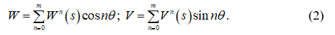
The expansion coefficients are determined by the formulas:
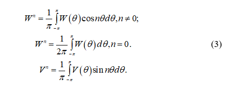
Figures 2-3 show the graphs of changes in the components of the load W(θ) and V(θ) and their approximation using series (2) with a different number of terms. The calculations were performed at γ = 26.5 kN/m3, φ = 220, R = 3 m, H = 2 m.
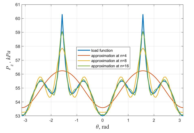
Figure 2. Change in the normal component of the load depending on θ and approximation of the function W(θ) using a series
Figure 3. Change in the tangential component of the load V(θ) and its approximation using the series
The calculation is performed separately for each member of the series with the subsequent summation of the results for each harmonic. For the terms corresponding to n = 0, the calculation is carried out as for an axisymmetric load according to the method proposed in [3]. In the case where the loads change as periodic functions, the displacements will also be periodic functions. For the calculation, an axisymmetric finite element in the form of a truncated cone is used, shown in Fig. 4, with 4 degrees of freedom at the node: displacements ![]() and rotation angles
and rotation angles 
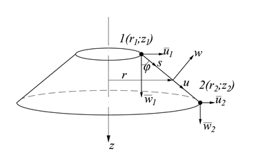
Figure 4. Conical finite element
The construction of the stiffness matrix and the load vector for each harmonic is discussed in detail in [4, 5].
Results and discussion. The calculation of the corrugated cylindrical shell with the radius R = 3 m and length L = 4 m was performed for the loads shown in fig. 2 and fig. 3. The corrugation shape was sinusoidal with a wavelength λ = 0.2 m and amplitude A = 0.0275 m. The shell was fixed at the ends in the direction of the global axes x, y, z. For comparison, the calculation of a smooth shell was also performed. When calculating by the semianalytical method, the number of finite elements was taken equal to 200. When expanding the load in a Fourier series, the first 10 even terms of the series were retained (the odd terms in the decomposition of a given load vanish).
Graphs of changes in internal forces Ns and Nθ along the length of the shell in the section θ = 0 are shown in Fig. 5-6.
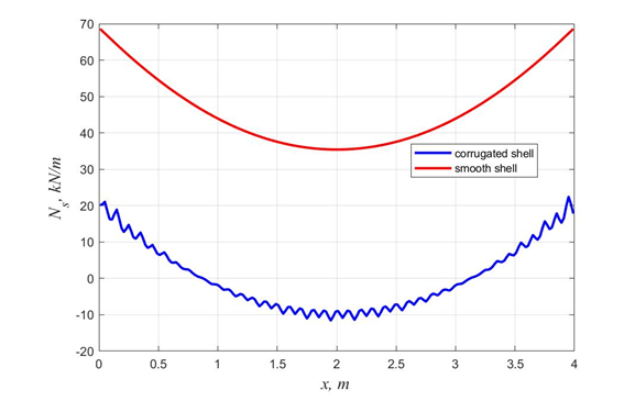
Figure. 5. Change in the meridional force Ns along the length of the shell at the cross section θ = 0
It can be seen from Fig. 5 that the meridional force Ns for the corrugated shell turns out to be significantly lower than for the smooth one. At the same time, for the annular force Nθ along the length of the corrugated shell, oscillations with a large amplitude are observed. The maximum values of the shear force Nsθ for the corrugated shell are slightly higher than for the smooth one; the graph of its change along the length at θ = π / 4 is shown in Fig. 7.
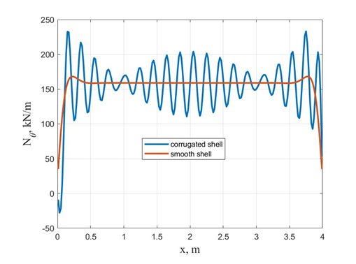
Figure 6. Change in the annular force Nθ along the length of the shell at θ = 0
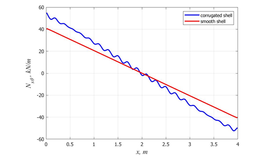
Fig. 7. Change in the shear force along the length of the shell at θ = π / 4
Conclusions. The results obtained show that when using simplified approaches (calculation using an arched model, replacing a corrugated structure with an orthotropic one), it is impossible to take into account fluctuations in internal forces, and as a consequence, there is an overestimation of the bearing capacity of metal corrugated structures. And in comparison with the classical FEM, the use of the semi-analytical finite element method can significantly reduce the computation time.
1. Kleyn G. K. Stroitel'naya mekhanika sypuchikh tel [Structural mechanics of bulk solids]. Moscow: Stroyizdat, 1977. 256 p.
2. Osokin I.A. Primeneniye teorii obolochek vrashcheniya k raschetu gofrirovannykh vodopropusknykh trub [Application of the theory of shells of rotation to the calculation of corrugated culverts] // Internet-zhurnal «Naukovedeniye». 2013. No. 2(15). URL: http://http://naukovedenie.ru/PDF/40tvn213.pdf.
3. Chepurnenko A.S., Yazyev B.M., Turko M.S. Raschet metallicheskikh gofrirovannykh obolochek pri osesimmetrichnom nagruzhenii [Calculation of metal corrugated shells under axisymmetric loading] // Inzhenernyy vestnik Dona. 2018. No. 3. URL: ivdon.ru/ru/magazine/archive/n3y2018/5134
4. Yanukyan E.G., Chepurnenko A.S., Yazyev B.M., Turko M.S. Calculation of Cylindrical Corrugated Shells Using a Semi-Analytic Finite Element Method // Materials Science Forum. 2018. Vol. 931. Pp. 3-8.
5. Chepurnenko A.S., Yazyev B.M., Turko M.S. Raschet tsilindricheskikh gofrirovannykh konstruktsiy pri pomoshchi poluanaliticheskogo metoda konechnykh elementov [Calculation of cylindrical corrugated structures using the semi-analytical method of finite elements] // Stroitel'stvo i tekhnogennaya bezopasnost'. 2018. No. 12(64). Pp. 49-56.
